Voltage Sag
What is Voltage Sag?
Voltage sag, also known as a voltage dip, refers to a short-duration reduction in the RMS (Root Mean Square) voltage level. Typically, it ranges from 10% to 90% of the nominal voltage and lasts from 0.5 cycles (approximately 10 milliseconds at 50 Hz) up to 1 minute. While the voltage does not drop to zero (as in an interruption), it falls low enough to affect the normal operation of electrical equipment.
Voltage sags are among the most frequent power quality issues in industrial, commercial, and even residential settings. They may not always be noticeable, but they can cause serious disruptions, particularly in environments with sensitive or mission-critical equipment.
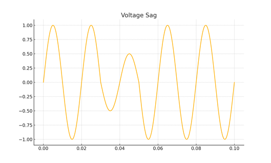
Figure: What is Voltage Sag?
Why Does Voltage Sag Matter?
Voltage sags can:
– Cause industrial drives or Variable Frequency Drives (VFDs) to trip or reset
– Interrupt sensitive equipment like PLCs, medical imaging systems, or servers
– Lead to misoperation of control circuits
– Reduce productivity through unexpected downtime
– Accelerate wear and tear on motors due to low voltage torque stress
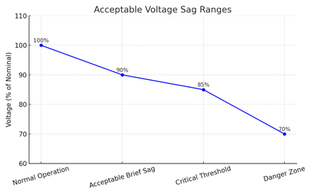
Acceptable Voltage Sag Ranges
The tolerance of equipment to voltage sags varies based on the type, sensitivity, and purpose. However, some general guidelines include:
– Normal Operation: 100% to 90% of nominal voltage
– Acceptable Sag: Above 85% for very brief durations (1–2 cycles)
– Critical Threshold: Below 85% may trip VFDs, reset electronics, or halt processes
– Danger Zone: Below 70% is very likely to disrupt most sensitive devices
Common Causes of Voltage Sags
Voltage sags often originate from sudden high current demands or external faults. Key contributors include:
– Starting large motors or compressors
– Short circuits on the grid or within the facility
– Transformer energization
– Capacitor or large load switching
– Utility faults and protection operations
Real-Life Examples
Plastic Plant: Starting multiple hydraulic pumps simultaneously caused a 68% sag, halting injection cycles and scrapping products.
Hospital CT Scanner: HVAC startup triggered a 75% sag, forcing diagnostic scans to restart and delaying patient care.
Data Centre: A 60% sag from a nearby grid fault rebooted unprotected servers, breaching SLA uptime.
University Lab: Fume extractor VFD startup sagged voltage, freezing a spectrometer mid-calibration and wasting samples.
Office Building: Elevator motor startup sagged voltage to 82%, flickering lights and tripping network devices.
Cement Factory: Simultaneous motor restarts sagged voltage to 65%, tripping kiln control PLCs and pausing production.
Pharmaceutical Lab: Utility transformer switching caused a sag that reset PLC-controlled dosing systems, spoiling a drug batch.
Printing Press: Air compressor inrush caused a 70% sag, faulting the main press and jamming paper.
FMCG Plant (Fast Moving Consumer Goods): Concurrent VFD loads sagged voltage, misaligning labellers and affecting packaging integrity.
Construction Site: Undersized generator on crane startup sagged power, resetting lights and site IT mid-operation.
Airport Ops: A lightning-induced sag disrupted HVAC and fire alarms, delaying gate clearance and passenger flow.
Retail Hypermarket: Generator switchover caused a sag to 60%, rebooting POS terminals and stalling checkout lines.
Practical Solutions
Soft Starters – Reduce inrush current during motor startup, minimizing voltage sags caused by sudden high demand.
Variable Frequency Drives (VFDs) – Provide partial ride-through capability by maintaining motor operation during brief sags using stored DC bus energy.
Static Voltage Regulators (SVRs) – Instantly correct voltage sags by electronically boosting the incoming voltage to maintain a stable output.
Uninterruptible Power Supplies (UPS) – Supply backup power from batteries or capacitors during voltage sags to keep sensitive equipment running without interruption.
Motor Ride-Through Solutions – Use energy storage (e.g. supercapacitors, flywheels) or DC link support to maintain motor torque and prevent trips during sags.
Power Quality Analysers – Detect, log, and quantify voltage sags to help identify their source, duration, and impact for effective mitigation.
Utility Coordination – Ensures facility loads and protection schemes are aligned with utility systems to minimize sag propagation and improve fault response
Voltage Swell
What is Voltage Swell?
Voltage swell is a short-duration increase in the RMS voltage level, typically rising between 110% to 180% of the nominal voltage and lasting from 0.5 cycles to 1 minute. Unlike voltage sags, which involve a temporary voltage drop, swells represent a sudden overvoltage condition.
While short-lived, swells can be just as disruptive — and potentially more damaging — especially to sensitive electronics, lighting systems, and power supplies not designed to handle overvoltage conditions.
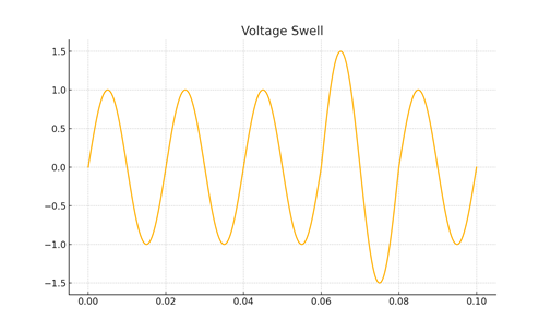
Figure: What is Voltage Swell?
Why Does Voltage Swell Matter?
Even a brief voltage swell can:
– Damage or reduce the lifespan of sensitive electronics
– Trip circuit breakers or protective relays unnecessarily
– Cause insulation breakdown in cables and transformers
– Lead to overheating in lighting systems and small motors
– Interrupt industrial control logic or trigger safety shutdowns
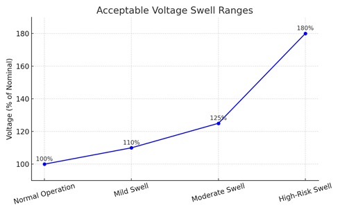
Acceptable Voltage Swell Ranges
– Normal Operation: Up to 110% of nominal voltage
– Moderate Swell: 110%–125% — may cause nuisance tripping
– High-Risk Swell: 125%–180% — likely to damage devices
– Critical Swell: Above 180% — very dangerous to all systems
Common Causes of Voltage Swells
– Sudden reduction in heavy loads
– Capacitor switching
– Phase-to-ground faults on ungrounded systems
– Utility switching or reclosing operations
Real-Life Examples
Textile Factory: Capacitor bank switching caused a 125% swell, burning out LED lights and tripping control panels.
Printing Press: An HVAC shutdown triggered a swell that damaged servo boards and halted a live print job.
Office Building: Elevator motor trip caused a voltage spike, frying the building’s router and small UPS system.
Pharma Cleanroom: Fixed PFC capacitors caused mild swells, hanging environmental control PLCs mid-process.
Retail Supermarket: Freezer trips led to a short swell that froze POS terminals and delayed checkouts.
School Lab: Utility-side switching triggered a 130% swell, crashing student PCs and damaging hardware.
Construction Site Office: Disconnecting a welding load from a genset caused a swell, damaging monitors and power strips.
Practical Solutions
Surge protectors or TVSS (Transient Voltage Surge Protector): Clamp overvoltage spikes and divert excess energy to ground, protecting sensitive electronics.
Static voltage regulators or line conditioners: Automatically stabilize output voltage during swells to ensure clean, consistent power.
Capacitor banks (auto PFC): Avoid fixed or oversized banks; use automatic step-controlled systems to prevent overvoltage during light loads.
Utility coordination: Helps identify and correct supply-side causes like improper tap settings or feeder switching events.
Power quality analysis: Monitor and log swell events for root cause analysis, protection tuning, and utility performance validation.
Voltage Interruption
What is a Voltage Interruption?
A voltage interruption is a complete loss of electrical voltage supply in one or more phases of a system. It differs from a sag (partial drop) or a swell (temporary rise) because the voltage drops to zero or near-zero levels. Interruptions can last for milliseconds to several minutes, depending on the cause and system protection responses.
Interruptions are often classified by duration:
– Instantaneous: ≤0.1 seconds
– Momentary: >0.1s to ≤2 seconds
– Temporary: >2s to ≤2 minutes
– Sustained: >2 minutes
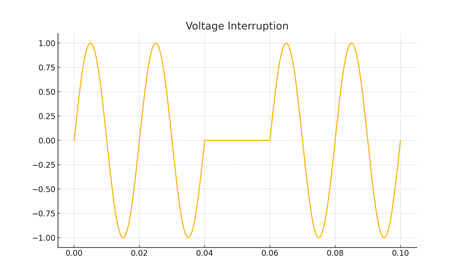
Figure: What is a Voltage Interruption?
Why Do Interruptions Matter?
– Complete equipment shutdown
– Process halts in industrial systems
– Data loss or corruption in IT environments
– Medical or safety system failures
Typical Causes of Interruptions
– Short circuits or ground faults
– Utility switching or protection operations
– Lightning strikes
– Blown fuses, tripped breakers
– Loose or corroded connections
– Maintenance or unplanned outages
Real-Life Examples
CNC Line: A breaker trip caused a 1.2s outage mid-operation, damaging tooling and halting production.
Hospital OR: A 5s generator delay led to critical monitor loss during surgery, forcing manual vitals checks.
Data Center: A 0.5s rack outage crashed virtual machines, requiring a 2-hour recovery process.
Pharma Plant: A 3s utility switch-off ruined an active batch, resulting in significant material loss.
Retail Store: A lightning strike caused an 0.8s blackout, risking refrigeration failure and rebooting checkout systems.
University Lab: A 2-minute power cut during maintenance erased student work and downed 20 terminals.
Construction Site: A genset stall caused a 6s outage, resetting safety systems and requiring manual override.
Solutions & Prevention
Uninterruptible Power Supply (UPS): Provides immediate backup power during interruptions, keeping critical systems online.
Automatic Transfer Switch (ATS): Switches between utility and generator quickly to minimize downtime during extended interruptions.
Dual Feed or Redundant Supply: Connects essential loads to two separate power sources for continuous operation.
Backup Generators: Provide sustained power during long interruptions; ideal for entire facilities or large load groups.
Energy Storage Systems (ESS): Batteries or supercapacitors bridge the gap between utility loss and generator startup.
Voltage Ride-Through Modules: Allow motors and VFDs to stay energized during short interruptions, avoiding restarts.
Power Quality Analyzers: Monitor and log interruption events to diagnose root causes and improve system design.
Harmonic Distortion – Client Guide
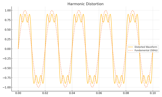
Harmonic Distortion
What is Harmonic Distortion?
Harmonic distortion occurs when current or voltage waveforms deviate from a pure sinusoidal shape due to the presence of harmonics — voltage or current components at integer multiples of the fundamental frequency (e.g., 150 Hz, 250 Hz if your base is 50 Hz).
A distorted waveform is the sum of the fundamental wave (50 Hz) and several higher-frequency waves riding on top of it.
This is typically caused by non-linear loads that draw current in abrupt pulses rather than smooth sinusoidal waves.
Why Does Harmonic Distortion Matter?
– Overheats transformers and neutral conductors
– Causes nuisance tripping in protective devices
– Increases losses in motors and cables
– Affects metering and control accuracy
– Reduces power factor and equipment life
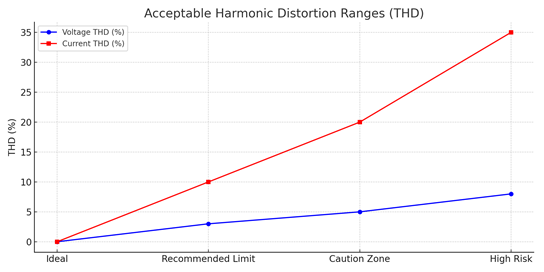
Acceptable THD Levels
– Voltage THD (Total Harmonic Distortion): Should generally be <5%
– Current THD: Depends on load type, but <20% is typical for non-linear equipment
Common Causes
– Variable frequency drives (VFDs)
– UPS systems and battery chargers
– LED lighting and electronic ballasts
– Rectifiers and switching power supplies
Real-Life Examples
Plastic Factory: VFDs without filters caused transformer overheating due to high 5th and 7th harmonics.
Data Center: UPS and SMPS loads created high THD on the neutral, leading to overheating and neutral conductor failure.
Retail Superstore: LED lighting and IT loads distorted voltage, causing flickering lights and register display errors.
Cement Plant: VFDs caused resonance in capacitor banks, leading to capacitor failure and equipment damage.
Hospital Imaging Lab: Non-linear loads from MRI and CT scanners caused voltage distortion and calibration errors.
University Lab: Harmonics from lab instruments interfered with PLC HVAC control, affecting environmental stability.
Practical Solutions
- Passive harmonic filters: Use tuned reactors and capacitors to block specific harmonic frequencies from entering the system.
- Active harmonic filters: Inject opposing current waveforms in real-time to cancel out a broad range of harmonics.
- K-rated transformers: Designed to handle high harmonic currents without overheating the neutral or core.
- Line reactors: Installed with VFDs to smooth current draw and reduce harmonic generation.
- Detuned capacitor banks: Prevent resonance by shifting the system impedance away from dominant harmonic frequencies.
- Load segregation: Isolate non-linear loads (e.g., VFDs, UPS) from sensitive circuits to minimize harmonic propagation.
- Power quality analyzers: Monitor THD levels and pinpoint harmonic sources for corrective action.
Voltage Fluctuations and Flicker
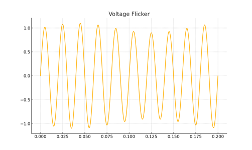
What is Voltage Flicker?
Voltage flicker refers to rapid and repetitive small changes in voltage, which can cause noticeable variations in the brightness of lighting systems. These fluctuations do not usually affect the average RMS voltage but lead to perceptible discomfort, especially under fluorescent or LED lighting.
Why Does Voltage Flicker Matter?
– Causes visible light flicker which is irritating and distracting
– May disrupt sensitive production processes involving lasers or microscopes
– Can cause visual fatigue or even trigger photosensitive conditions
Acceptable Limits
– Flicker severity is quantified using the short-term flicker index (Pst)
– IEC 61000-4-15 recommends Pst ≤ 1.0 for public low-voltage systems
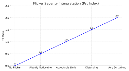
What is Pst (Short-Term Flicker Severity Index)?
- Pst = “Perceptibility short-term”
- It is a numerical index that expresses how noticeable voltage flicker is to the average human eye over a 10-minute period.
- It accounts for:
- Flicker frequency (how fast)
- Flicker depth (how much the voltage fluctuates)
- The human visual response curve (some flicker frequencies are more disturbing than others)
Common Causes
– Arc furnaces
– Welding machines
– Large motor startups
– Rapid load switching events
Real-Life Examples
Steel Plant: Arc welders caused visible light flicker, leading to eye strain and reduced worker focus.
Retail Mall: Frequent escalator and lift use triggered LED signage flicker and customer complaints.
Hospital Lab: Compressor switching flickered ceiling lights, disrupting microscope calibration.
School Lab: A shared water pump circuit caused monitor flicker, leading to student eye strain.
Plastic Factory: Cycling chillers caused flicker over task lights, affecting sealing accuracy.
University Lab: Old lab gear on unbalanced phases disrupted photometry with visible flicker.
Practical Solutions
- Soft starters or VFDs: Reduce voltage inrush during motor starts, minimizing abrupt fluctuations.
- Dedicated transformers or feeders: Isolate flicker-causing equipment (like welders or chillers) from sensitive circuits.
- Voltage regulators or line conditioners: Smooth out small voltage deviations that would otherwise reach lighting or electronics.
- Flicker meters and analyzers: Measure short-term flicker index (Pst) to quantify and locate sources of visual disturbance.
- Phase balancing: Distribute single-phase loads evenly across phases to prevent load-induced voltage swings.
- UPS for lighting or lab equipment: Maintains constant output voltage during rapid source variations.
- Automatic load management: Staggers high-inrush load startups to avoid overlapping voltage dips.
Voltage Unbalance/Imbalance
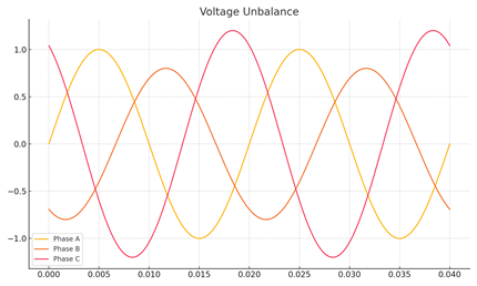
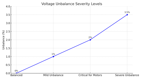
What is Voltage Unbalance?
Voltage unbalance refers to a condition where the magnitudes or phase angles of the three-phase voltages are not equal. In a balanced system, the three phase voltages should be equal in magnitude and 120° apart in phase. Unbalance is typically expressed as a percentage and calculated using the deviation of the lowest phase voltage from the average.
Why Does Voltage Unbalance Matter?
– Causes excessive heating in three-phase motors
– Leads to reduced motor efficiency and lifespan
– Increases energy losses and torque pulsations
– May cause nuisance tripping or vibration in equipment
How It’s Calculated
Per NEMA definition:
INSERT CALCULATION
Even a 1–2% unbalance can drastically impact motor performance.
Acceptable Limits
– IEC and IEEE standards recommend keeping voltage unbalance below 2% for most systems
– Sensitive motors may require even tighter tolerances (<1%)
Common Causes
– Unequal distribution of single-phase loads across the phases
– Faulty connections or open phases due to phase loss or blown fuse
– Issues at the utility side (transformer taps, feeder imbalance)
– Unbalanced capacitor banks or welders
Real-Life Examples
Plastic Factory: Uneven HVAC and lighting loads caused 1.7% unbalance, tripping motors during peak shifts.
Welding Workshop: A blown fuse left motors on two phases, overheating and damaging the welder transformer.
Pharma Lab: UPS loads on an unbalanced panel introduced noise, disrupting sensitive instrumentation.
Office Building: One phase overloaded with lighting and servers led to voltage dips and IT instability.
Construction Site: Improper phase taps caused tool stalling and heat buildup, delaying operations.
Hospital Imaging: A 2.2% unbalance from shared elevator/CT loads rebooted a scanner mid-scan.
Practical Solutions
Load redistribution: Evenly distribute single-phase loads across all three phases to reduce imbalance at the panel or feeder level.
Phase monitoring relays: Detect and trip on unbalanced or lost phases to protect motors and critical loads.
Transformer tap correction: Adjust utility or internal transformer taps if one phase consistently runs higher or lower.
Dedicated circuits for large single-phase loads: Prevent distortion and imbalance by isolating high-load devices like pumps or HVAC units.
Voltage regulators or balancing transformers: Automatically compensate for unbalanced input to maintain balanced output.
Regular thermal and PQ audits: Identify loose connections, blown fuses, or worn contacts that contribute to imbalance over time.
Three-phase power analyzers: Continuously monitor phase voltages and alert maintenance teams when thresholds are breached.
Transient Overvoltage
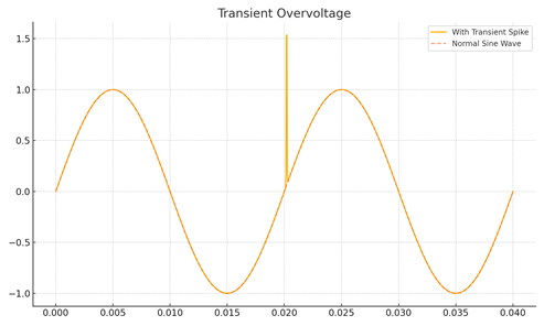
What is Transient Overvoltage?
A transient overvoltage is a brief, high-amplitude spike in voltage that typically lasts only a few microseconds to milliseconds. These surges can reach several kilovolts and are not part of the normal sinusoidal waveform. They are also known as spikes, surges, or impulses depending on their shape and cause.
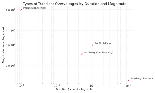
Types of Transients
- Impulsive: Single-directional spikes (e.g., from lightning)
- Oscillatory: High-frequency disturbances that decay (e.g., from switching)
Why Do Transient Overvoltage’s Matter?
– Damage sensitive electronics, power supplies, and control circuits
– Degrade insulation in motors, transformers, and cables
– Cause data corruption or resets in PLCs and digital systems
– Trigger nuisance tripping of protective devices
Common Causes
– Lightning strikes (direct or indirect)
– Capacitor bank switching
– Fault clearing by circuit breakers
– Load switching, especially inductive loads
– Electrostatic discharge (ESD) or arcing events
Why It’s Dangerous
Transients cause:
- Instantaneous damage to semiconductors and low-voltage control circuits
- Breakdown of insulation in motors and transformers
- Data loss or corruption in unprotected electronics
- Hidden degradation in devices even if immediate failure doesn’t occur
Real-Life Examples
Plastic Factory: Capacitor switching caused a 2.5 kV spike, resetting PLCs and halting production.
Hospital Radiology: A lightning-induced surge corrupted CT scan data, forcing patient rescheduling.
Retail POS: ATS switchover triggered a transient, rebooting registers and delaying checkout.
University Lab: Transients from nearby welding froze a microcontroller test bench, disrupting research.
Office IT Room: HVAC contactor switching caused UPS undervoltage logs and event flagging.
Construction Site: Arc flash from a switchboard created a surge, tripping lights and tools mid-operation.
Practical Solutions
Surge protection devices (SPD): Divert transient energy to ground within microseconds, protecting connected loads from lightning or switching spikes.
TVSS (Transient Voltage Surge Suppressors): Clamp high-voltage transients before they reach sensitive circuits, often used at panel and equipment level.
Type 1/2/3 SPDs: Layered protection strategy — Type 1 at main service, Type 2 at distribution boards, Type 3 at individual devices.
EMI/RFI filters: Suppress high-frequency transient noise generated by switching loads or nearby arc sources.
Shielded power cables: Reduce induced surges from electromagnetic coupling, especially in control and instrumentation circuits.
Isolated or filtered UPS systems: Provide surge-isolated power to critical systems with clean, regulated output voltage.
Proper grounding and bonding: Ensures transients have a low-impedance path to earth, enhancing SPD and filter effectiveness.
PQ analysers with high-speed sampling: Detect and log transient events for root cause analysis and verification of SPD performance.
Frequency Variations
What is Frequency Variation?
Frequency variation refers to any deviation from the standard nominal power system frequency — typically 50 Hz (in most of the world) or 60 Hz (in some regions).
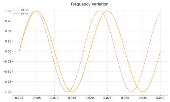
It reflects the balance between power supply and demand:
- Overgeneration → frequency rises
- Overloading → frequency drops
In stable grids, frequency is tightly controlled within ±0.1 Hz, but even small deviations can affect equipment that depends on precise timing.
Why Do Frequency Variations Matter?
Motors and generators rely on steady frequency for speed control
UPS and inverters synchronize to grid frequency
Sensitive electronics (timers, clocks, VFDs) can misoperate
Long-term deviations affect synchronization and system protection
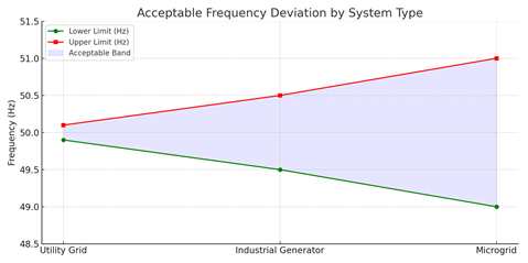
Acceptable Limits
– For most utilities: ±1% (49.5–50.5 Hz) for short durations
– Critical processes (e.g., in manufacturing or data centers) often require tighter thresholds: ±0.1 Hz
Common Causes
Generator undersizing or governor instability
Rapid load shedding or disconnection
Islanded operation or loss of utility connection
Generator synchronization failure
Intermittent renewable sources (without buffers)
Real-Life Examples
Food Plant: Underloaded genset caused frequency to rise to 52.3 Hz, misaligning packaging lines.
Hospital: Generator lag caused a dip to 48.2 Hz, rebooting imaging systems and delaying procedures.
University Lab: Microgrid frequency drift disrupted instrument timing and test validations.
Office Building: Rooftop solar inverter drifted to 51.5 Hz after grid disconnect, halting power output.
Construction Site: Generator overloaded by welders caused 47.8 Hz sag, stalling tools mid-cut.
Practical Solutions
Generator governor tuning: Ensures accurate frequency control under load changes by adjusting fuel/engine response.
Automatic load banks: Add or remove dummy loads to stabilize frequency on lightly loaded generators or microgrids.
Flywheel or battery energy storage (ESS): Absorbs or injects power instantly to correct short-term frequency deviations.
Frequency ride-through UPS: Maintains stable output during minor frequency drifts, preventing equipment reset.
Droop control in multi-gen systems: Shares load proportionally to prevent overcompensation or conflict during parallel operation.
Synchronized load management: Staggers load startups to prevent generator dips or frequency swings.
Frequency monitoring relays: Detect excursions beyond preset thresholds and trigger load shedding or alarms.
Poor Power Factor – Client Guide
What is Power Factor?
Power factor (PF) is the ratio of real power (kW) to apparent power (kVA) in an AC electrical system. It measures how effectively electrical power is being converted into useful work output.
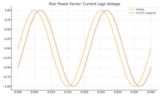
A poor power factor means that more current is required to do the same amount of useful work, leading to energy inefficiency and increased strain on the electrical infrastructure.
– Unity PF = 1.0 (ideal)
– Lagging PF (< 1) occurs in inductive loads (motors, transformers)
– Leading PF (< 1) occurs in capacitive loads (lightly loaded cables, capacitors)
Why Does Poor Power Factor Matter?
– Increases in electricity bills due to higher demand charges
– Overloads of cables, transformers, and generators
– Causes voltage drops and reduced power quality
– Triggers penalties from utilities (common in industrial setups)
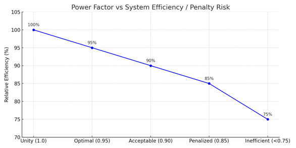
Acceptable Limits
– Most utilities require PF ≥ 0.9
– A PF below 0.85 is often penalized
– Critical systems aim for 0.95 or better
Common Causes
– Inductive motors running under low load
– Uncorrected welding machines and HVAC systems
– Overuse of VFDs without filters
– Poorly designed or aging power factor correction systems
Real-Life Examples
Steel Mill: Underloaded motors dropped PF to 0.68, triggering utility penalties and transformer overloads.
Office Building: Fluorescent lighting and UPS loads caused 0.78 PF, overheating neutral conductors and failing compliance tests.
Cold Storage: Compressors running at low load led to poor nighttime PF, raising kVA charges and straining generator transitions.
University Campus: Uncorrected pump and fan loads caused 0.72 PF, tripping the main transformer under low load.
Pharma Lab: Aged capacitors and VFDs caused unstable PF, correlating with voltage sags and control instability.
Practical Solutions
- Automatic capacitor banks: Inject reactive power to offset inductive loads and improve PF dynamically based on demand.
- Detuned harmonic filters: Prevent capacitor banks from amplifying harmonics while correcting PF in systems with non-linear loads.
- Static VAR compensators (SVC): Electronically controlled devices that supply reactive power in real-time for rapid PF correction.
- Synchronous condensers: Overexcited motors running without mechanical load to improve PF in high-capacity systems.
- Local (load-level) correction capacitors: Installed close to motors or machinery to reduce current draw and local voltage drops.
- Power factor controllers: Monitor system PF and switch capacitors in or out to maintain a set target.
- PQ analyzers and energy meters: Continuously track PF trends and support long-term optimization.